
DIY Subkick Mic

Background
The following is a (somewhat) updated version of an article that I wrote almost 15 years ago about how to build your own SubKick microphone. I was curious about the different ways in which people go about making these, and since they are a relatively simple build, I tried to embellish with some additional aesthetic features and a few simple mods.
For those who may not have come across this idea before, the concept is fairly straightforward. Mechanically speaking, there is not a whole lot of difference between a moving coil dynamic loudspeaker and a moving coil dynamic microphone. Both rely on the theory of electromagnetic transduction to convert voltage into sound, or sound into voltage.
Moving-coil loudspeakers are a great example of how this theory is used in audio applications. Typically, they are used to transform an electronic representation of sound (Audio) into something which can be heard (Sound). To simplify its basic working mechanism; A audio signal is sent to a coil of wire that is suspended around a permanent magnet. As the audio signal (voltage) changes from positive to negative (alternating current), the coil reacts by moving back and forth towards the various poles of the magnet that propagate the attracting force (negative to positive and visa-versa). The other end of this coil is attached to a diaphragm that is sometimes referred to as a cone or driver. As the coil moves from one pole to the next, it causes the air in front of and around the cone to either increase in pressure as it moves forward, or create a vacuum of pressure when the cone retreats backward. These oscillations in air pressure creates what we perceive as audible sound.
A dynamic microphone is essentially the same working-mechanism. The only difference is that a microphone is supposed to capture acoustic energy and transduce it into electrical audio signal. In this case the construction is more or less the same except that the diaphragm is much smaller than the cone of a typical loudspeaker. Disturbances in air pressure cause the diaphragm to move back and forth. Since the diaphragm is connected to the coil of wire, this causes the coil to move across the magnet thus creating alternating current in the coil.
Since there is no basic difference between a speaker an a microphone, then it stands to reason that one could take the place of another. (If you ever wish to be daring, you can experiment with this idea by hooking up the output of a pair of headphones into the input of a microphone pre-amp and speaking into one of the ears…D.J.s have been doing this forever.)
While it’s possible to achieve transduction using a speaker as a mic, the fact is that speakers really don’t sound that good in reverse. But speaker cones cover more physical area and that makes them better at capturing large disturbances in air pressure. When recording instruments where low frequencies are critical such as a kick-drum or bass amp, speaker drivers can be more efficient at capturing the energy of glorious sub-frequencies just out of reach of dynamic and condenser mics. Used on their own, sub-kick mics aren’t that clear a representation, but when added in moderation to dynamic or condenser mics on to the beater head and shell, a more skull-shaking low end can be achieved.
Engineers have been building these things for decades, so it’s not a new idea. In fact, Yamaha has a sub-kick mic that is now being manufactured and sold for around $400.00. It’s always easier to buy one, but building one yourself is easy and shouldn’t cost you a whole lot. I built the one featured in this article for about $25, and it sounds every bit as awesome as the $400.00 model. (The difference, I think, must be in the materials for the shell and the fancy logo on the front.)
In this how-to article, I’ll be showing how I built my own, but I encourage anyone interested in building one for themselves to take some time to research and experiment and come up with their own design. As I have mentioned before, some of my ideas are not unique, so I’ll do my best to include links to resources where possible.
Also, I will list some parts as being available at amazon.com. If you want another good resource, www.digikey.com is a great online dealer for just about any and everything electronics based under the sun.
So without further ado, here’s how to make your very own sub-sonic functioning work of art:
Materials List:
(1) 10″ subwoofer driver (8 ohm)
(1) 10 1/4″ Cardboard Sonitube concrete pillar forming tube
(2) XLR recessed male wall mount
(1) DPDT Submini Toggle Switch
(1) Mini Breadboard (radio shack)
(2) 1/4 Watt 470 ohm resistors (1-2%)
(1) 1/4 Watt 100 ohm resistor (1-2%)
Soldering kit
24 gauge wire
8 zip-ties
Power drill and bits (3/4″ bit for XLR mounts, the rest standard sizes)
Tape Measure
Tight-Bond Wood Glue or Gorilla Glue. (Contact cement might work well too)
Dark Lead Pencil and a Sharpie marker
Spray paint (as many colors as you like)
(1) Roll of white, adhesive contact paper
(1) Roll of Blue painting tape
(1) Exacto-Knife (Type A with #11 Blades)
About the materials:
Speaker: I decided to use a 10″ sub-woofer for my speaker element, mainly, because it’s what I had lying around at the time. From my research, I found that there are some things to consider when choosing a speaker. First off, there’s no need to buy anything expensive. The main things to consider are the size of the cone and the stiffness of the material that the cone is made out of. I’ve read that it’s not advisable to use anything smaller than a 6″ cone, as 4″ is really too small to capture the low frequency waves we’re looking for, and because as you get smaller, the speakers get lighter and will distort quicker. Anything larger than 10″ is really getting to be large enough to be in the way of other mics and will probably get a little heavy.
Another thing to consider is that stiffer cones don’t have as much flex as softer rubber gasket cones and are less responsive.
Electrical Components: Get the nicest components you can. You don’t need many of them, and they aren’t expensive.
Shell Enclosure: Some people prefer to make their speaker housing out of a wooden drum shell. This is actually what I wish I could’ve done, but I didn’t have one available and rather than spend $40 on one, I thought I would try my best to make do with what cheap materials I could find. The cardboard concrete form tube turned out to be perfect and only cost me $7.00 at the Home Depot.
How it comes together…
Part 1: Making the Shell
This is an important step. If you cut corners or settle for sloppy work in this phase, it will degrade the strength of your completed piece, so make sure you have plenty of time set aside for this step. To allow for proper drying time for the glue, I would recommend that you carve out at least a 24hr period to complete this task.

The first thing to do is to measure and cut your shell materials. I like these cardboard form tubes because they are cheap, easy to find and they are NOT precise. If you find the 10″ forms at the Home Depot, you’ll notice that some of them are actually telescoped inside of each other. I think the official tolerance is something like within 1/4″. I suggest bringing a tape measure with you to home depot. (If you don’t hang out at Home Depot much then this actually works out great…just wear jeans and a flannel shirt and boots and clip the tape measure to your belt…you’ll look like a regular).
If you’re planning on using a 10″ speaker, try to find a form that is a little wider than 10″. If you get a 10″ tube, the speaker wont fin in very well. I used one that was 10 1/8″ in diameter.
Once you’ve secured a tube, you’ll need to measure out a depth to cut from it. If you got the tube at the Home Depot, you’ll probably need to cut a new edge from one side as they have a tendency to get dinged up pretty bad in shipping. (these are used to form concrete)
To measure the correct depth to cut so that it will fit your speaker, set your driver on a flat surface on its magnet so that the speaker is facing up. Then, using your measuring tape, record the distance from the surface to the top edge of the speaker. Add about a half an inch to that number. This is how deep your tube needs to be cut. Starting from the cleanly squared end of the tube, measure the depth and mark it with a sharpie or pencil.
To make the cut, you can use a hand saw if you have one, but I prefer to use my table saw.

PLEASE NOTE: Tablesaws are dangerous, and I cant stress safety enough. If you have not used a table saw before, don’t try this! While they are a great tool, without the proper safety training, you can get really hurt or even killed using them, so I mean it: ONLY ATTEMPT TO USE A TABLESAW IF YOU HAVE HAD THE PROPER TRAINING! I hereby assume no liability for injuries caused by using a table saw to complete this project.
If you have to use a hand saw, try to make your cut as square as possible.
If using a tablesaw; set your fence for the depth of the cut and push the square edge against the fence. Raise your blade to 1/2″ above the thickness of the tube. Slide the tube across the blade until the blade is in the middle of the tube, then spin the tube a few inches at a time and continue feeding across the blade until the entire circumference has been cut.
This will render the outer shell. But unless your speaker magnet is REALLY weak and light, this will not be strong enough to properly support the speaker or stay put on a stand, so we’ll have to reinforce it with another layer of cardboard. At 2-Ply, this should be strong enough to keep things supported and will also ensure that this baby lasts. Of course, there’s nothing keeping you from going 3-ply if you choose…
To make the shell 2-ply, you’ll need to cut a second section to the same depth as the first.

Next, orient the second shell so that it is now 90 degrees from the original cut, and make a slit along the edge of the shell.

This should now allow you to collapse the diameter of the second shell and fit it inside the first. There will be some overlap of the edges. Take a box cutting knife and carefully cut the excess so that there is no longer any overlap. I recommend marking the edges where you can see the overlap and then use a metal ruler to cut a straight line. It’s thick cardboard, so the trick is to make multiple passes along the same cut. Eventually, you’ll break through and will be rewarded with a clean seam.

Next, you’ll have to secure the slitted one inside the outer. This part is a bit tricky. It’s important to use a glue with a slower drying time. This will give you some extra tweaking time to help position the two inside each other so that the edges are just right. I used Tight-Bond type 1 Wood Glue, and would highly recommend it. (Also, make sure you do this part on a workshop surface you don’t mind getting messy.
(WORD OF ADVICE: NEVER glue anything on top of your table-saw or nice counter tops because it’s very likely that glue will drip and ruin a finished surface!)
Start by applying glue in a wave pattern all around the inside of the outer shell. Really make sure you cover the surface as best you can. When it comes to laminating cardboard, remember that it’s an absorbant material and can take extra moisture.

I made my glue look like a sign wave….(nerd)
Constrict the inner shell so that its small enough to fit inside the larger outer shell, then slowly let go to allow the smaller shell to expand into the bigger shell. Make sure your seams are lined up and try twisting the inner layer against the outer layer. This should help spread the glue around and help to bond the two layers together as the glue dries.
You’ll need just about every clamp you might own for this next part. There should be some springy force from the inner section against the inside of the outer shell, but just to be sure there’s adequate pressure, use some moderately tightened clamps about every 4-5 inches all the way around the shell.
BE CAREFUL NOT TO OVER-TIGHTEN! Because we’re working with cardboard, there will be permanent circle indentions where the clamps were if you squeeze too hard.
Drying time…If you read the bottle of glue, it will tell you that it will dry in a half an hour and be ready to work with in about three. Don’t fall for it. Leave this baby clamped up for a minimum of 12 hours. I would recommend 24 if you can muster up the strength. It’s also a good idea to leave it in a dry place. Moisture in the atmosphere leads to longer drying-time. Avoid basements and garages if you can as these tend to be pretty damp and humid. My favorite is a full day of sunshine outside if the weather permits, followed by a night inside on newspaper next to a floor vent.
Part 2: Detailing the Shell
Here’s the part where you get to make your sub-kick look its best. Just like the last section, rushing is not always a good idea. Make sure you allot enough time to work on this so that you’re not hastily making decisions or trying to work with paint that isn’t dry yet.
My approach on this one was simple. Since we’re building this thing from found parts and cardboard I wanted to give it a low-fi look but still have a level of sophistication. I chose spray-paint because it’s easy to get, comes in a wide variety of colors, dries fast, works relatively well on cardboard and would give me a low-fi feel. I decided to create a logo and use a second color to add contrast.
The first thing to do is to find a base color. I decided to use a deep burgundy red. Clean the surface of your shell so that there is no sawdust and that there is a clean, smooth surface to apply the paint to. In a well ventilated area, apply a gratuitous layer of gesso or primer. This will keep the bright yellow of the tube from tarnishing the color of my red. I ended up using the Killz spray primer.
Next, coat the inside and outside surfaces with your base color. This might take two coats with about 45 minutes in-between to allow for proper drying time. Just like with the glue, the dryer the space, the quicker the dry-time will be. Also, beware of floating dust particles. Outside is risky as there’s a lot of junk that might embed itself into your paint job.

For me, stenciling is a lot of fun. I decided to design a logo for the mic so that it would have some character. I played around with a few images in photoshop and eventually came up with a logo design that I was happy with and that also worked in 2-tone.
If you have photoshop chops, this can be a lot of fun, so prepare yourself for a potential time-sink. If you don’t have photoshop, you can come up with some pretty cool stuff in MS Word, or heck, you can just draw your own with pen and ink if you want.
To make the stencil transfer, I printed this image out in black and white onto a sheet of contact paper that I cut to 8.5″ by 11″. BE ADVISED: This only works if you have a laser printer! If you have a standard ink printer, the ink will just bead-up and wont actually sink into the surface. This will create a huge pain in the butt when it comes time to cut your stencil. (Also, the ink will smudge on your fingertips and might prompt people to wonder if you spent the night in jail)
Also be warned, stenciling with contact paper is more accurate on hard, smooth surfaces. It’s probable that you’ll have less clean lines if you work with aerosol paints on contact paper on cardboard. For me, I want the rough street look, so I’m hoping that this will get me there but still not be too sloppy.
When your base color coats have dried, print out your stencil and adhere it to the side of your shell. I decided to add stripes around the edges to help camouflage the grip ties I’ll be using later, so I wrapped the rest of the shell in blue painters tape leaving about a half and inch around the top exposed.
Using the Exacto-Blade, trace out the black parts of the print and remove the sticky parts leaving the color beneath exposed. As you work, be careful not to push the blade too deep as you will damage the cardboard and may even cut yourself.
Take some time to apply some light pressure around your cuts to try to seal the edges as tightly as possible so that paint wont seep in and ruin your lines too badly.
When you’re done, you should think about whether or not you want to paint the inside the same color as the outside second tone.
You’re now ready to spray the second color over the stencil. For this, I decided to use a latex spray paint as it has a smoother finish and will contrast against the background color better. Also, I find that latex paint tends to stick to itself when it’s dry and lines can be cleaned up nicely with a quick and light pass of an exacto blade when you lift the contact paper up.

When the second color is dry enough, go ahead and apply a second coat. It’s nice to build up some paint here so that it lifts ever so slightly from the base coat. It gives a subtle beveled look to the surface.
After some touch-up work, the next step is to seal the paint-job with some clear-coat protectant. I used an aerosol version, but you certainly could use a paint brush and some clear-coat enamel also if you prefer to be more eco-friendly. (I’m still feeling pretty guilty about my carbon footprint for this project…)
Part 3: Designing and Building the Electronics
I don’t want to get too mired down into the details of explaining electronic theory as that’s not really my forte, and I feel it’s best left to others more experienced than me to do a better job explaining it. If you’re just starting out and are really curious or need a primer on the topic, I would recommend you visit HTTP://WWW.NDT-ED.ORG/EDUCATIONRESOURCES/HIGHSCHOOL/ELECTRICITY/HS_ELEC_INDEX.HTM. It’s not critical knowledge for building a sub-kick, but for me, it’s always more fun to build something when you understand how it works.
Building an electronics circuit is the simplest part of the construction. The goal here is to provide an electronic output for your signal that most represents that of a microphone. You can achieve this by simply connecting the positive terminal of the speaker to pin two of an XLR output and the negative terminal can connect directly to pin 3. Since there is no connection of the speaker to the ground, nor is there any preamplifier that would draw erroneous electrons into the fray, there is really no need to use a ground connection. Of course, if you wanted to, I suppose you could simply solder a ground wire to the speaker housing and run it to pin 1, though from my perspective, there’s really no direct benefit to doing this.
One issue that most people report having with their sub-kick mic is that the signal tends to come in really hot. Most people correct this by implementing a -20db pad at the mic preamp. This is due to the fact that the amount of voltage being created by the movement of the speaker is way beyond the amount of signal a microphone’s diaphragm typically generates. This is usually expressed in terms of impedance (noted in ohms). When a mic preamp sees more voltage than it’s capable of handling, it will distort.
One of the things that frustrated me for a while is that mic preamps in general are not manufactured with a standardized input impedance setting. Each manufacturer builds their preamp with a different setting and with different input impedances in mind. Some, like Universal Audio, build preamps with variable input impedance selection so that the preamp can be used with a wide variety of signals ranging from relatively high impedance signals from ribbon microphones or low impedance signals from tube mics. Essentially, this means that if the output of your microphone is not matched properly with the input impedance of your mic preamp, then you will have a voltage drop between the mic and preamp which translates to an audible shift in frequency response from the microphone.
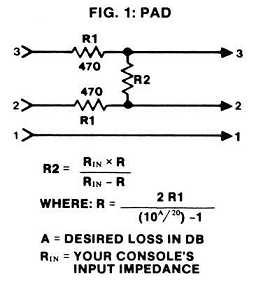
It therefore makes sense that we should try to make the output signal from the speaker match the type of impedance that a microphone would typically output. This is done by implementing a simple pad. The design for my pad construction came from an article published by Ethan Winer in the 80’s and can be found here: HTTP://WWW.ETHANWINER.COM/GADGETS.HTML. I think this is a fantastic site for very basic DIY buffs. It includes basic circuit diagrams for pads, phantom power supplies, direct boxes and more. Below is a picture of the circuit diagram from Ethan’s site that I used in my construction.
The really nice thing about this design is that it allows you to calculate the circuit so that it is optimized for your favorite console or mic pre’s input impedance.
As a side note, this same circuit can be used as an inline pad if you buy a switchcraft swfm 3 housing that acts as an XLR coupler. The resistors can be soldered across the pins of the female or male connectors. This comes in really handy when you’re in a session and are working with a mic that has a really hot output.
For my construction, I wanted to create an output impedance that is approximately 20db less while maintaining a value consistent with most dynamic microphones. To do this, I changed the value of R1 to 500 ohms and the value of R2 to 1,000 ohms. When added together, the combined resistance load of R1 and R2 will create an output impedance of around 150 ohms and a drop in a little more than 20db. Since the input impedance of my console is 1,200 ohms this should match pretty close since the rule of thumb is that generally, the output impedance of a microphone should be 10 times less than the input impedance of your mic preamp. The matching of impedance is more important to me than achieving exactly 20dB of signal loss.
It did occur to me that there may be times when I would want a really hot output signal from this mic. Recently, I’ve just skipped the mic preamp stage and inserted the mic directly into my AD converters. The signal is strong enough on its own that an additional boost isn’t really necessary, and I like the way it sounds un-boosted. Try it! You might be surprised at how nice and open it sounds.
The design of this subkick comes with options. Rather than just have one output with the pad, I decided to include two outputs, one that could be sent through the pad switch and one that would come directly off the speaker. For this, we use a simple DPDT toggle switch. You can find these readily, and cheaply.

These switches have three rows of two terminals. The middle two can be thought of as the input for a positive and negative signal. The top two can be thought of as output 1 and the bottom two can be thought of as output 2. The switch will activate one output or the other depending on its position
This configuration is shown in the wiring diagram above.
I would recommend constructing the pad circuit on a small breadboard, however they can also be connected directly to the terminals of the xlr connector. I decided to use a breadboard. Personally, I find it’s easier to make solid connections this way rather than trying to connect bare wire to a resistor.
Just be careful not to solder any terminals to the xlr connections until after they have been installed into the shell as you wont be able to fit the assembly through the holes otherwise. Just leave them open for now, and solder the assembly to the speaker terminals.
Part 4: Installing the circuit into the shell

Now it’s time to install the xlr connectors into the shell and wire-up the build. Find a 3/4″ drill bit and drill two evenly spaced holes into the side of the shell.
Decide where you want your holes to be in relation to how it will hang and where the logo is. I decided to locate mine 90 degrees counter-clockwise from the logo. Since I want my logo to face up, this will keep the wires dangling to the side and not underneath where they could limit hight adjustment.
As you drill, be careful not to apply too much pressure. Because we’re drilling into cardboard, it’s also best to start from the outside of the shell and drill to the inside. This will keep the cardboard from tearing-out on the show side and ruining your nice painted finish. Drill in short bursts and clean the excess cardboard off of your bit as you go. This will keep the hole’s edges clean. If there’s any tear out when you’re done, use the exacto blade to clean it up.

Drill a small hole between the two XLR holes where the toggle switch is to be located. You can then insert the toggle and make sure you orient the switch position to point to the correct output jack.
Using the exacto-blade to clean the edges of the inside of your hole, you should be able to insert the switch with no problems. If your switch is a little small, you may need to bore out a wider hole from the inside so that the threads poke through enough to affix the washer and nut on the outside.

Next, you need to insert the XLR jacks and mark smaller holes where the screw holes should be. I went to the Home Depot and bought small machine screws with matching nut and washers to hold the housings tightly against the cardboard. You cant use woodscrews because the threads wont hold very well in cardboard. You also need adequate washers to keep the nuts from embedding into the cardboard too far; causing the whole thing to rip out.
Again, Be ginger with the drill. Too much pushing will lead to tearout.
Now that the hardware is in place, you can go ahead and solder your XLR connections. Make sure that the positive terminals go to pin 2 and the negative terminals go to pin 3. Again, since there is no need for a ground, pin 1 can remain open.

You are now ready to fit the speaker into the shell so that the speaker is facing straight up and the shell is oriented with the logo right side up.
Using your exacto-knife and a good eye, look for the screw holes in the mounting bracket of the speaker and then trace down the side of the shell a little more than 1/2″ from the top (or about an 1/8″ below the stripe) and bore a small pin-hole marker. This is where we’re going to drill the holes that the grip-ties will go in to suspend the speaker in place in the shell. Go all around the speaker, and wherever there’s a hole in the bracket, make a mark on the shell.
When this is done, remove the speaker from the shell and drill out those holes using a bit that is as close to the width of the grip-ties as possible. We’re looking for a snug fit here, so it’s ok to be tight.
Now flip the speaker over on its face, and put the shell upside-down over it. Insert a grip tie through the mounting holes of the speaker from above and lace the open end around the front-lip and back in through the hole you just drilled. As you insert the grip-tie, make sure that it stays loose. If you tighten too much right-away, you’ll lose valuable maneuvering room that will be critical to getting all the way around to the holes on the other side.
When they have all been laced, pull the ends tight as you can. That’s it. It’s completed. Hook it up to your favorite mic pre (or converters) and test each output.
Like what you hear? Write me an email and let me know about it.
I hope that this guide has you wanting to try this yourself. If you’re a student or a pro looking to spice up your mic-locker, this is an awesome project and I had a blast doing it. Please, email me photos of your own builds.
Happy building!
